SEDIMENTATION PLANT
3P HYDROSHARK
Full flow treatment without separating structure
Areas 500 m² – 35,000 m² Combination structures unlimited
Volume flows up to 875 l/s for combination structures unlimited.
Qmax up to 1,100 l/s
POLLUTANTS
Trash and debris*
Microplastic**
Total suspended solids (TSS)***
Mineral-oil hydrocarbons (MOH)
*** Particle size d50= 122μm
REMOVAL
> 99%
> 99%
> 94%
> 98%
OVERVIEW HYDROSHARK / TECHNICAL DATA

3P Hydroshark
750
FOR INSTALLATION IN A
CONCRETE SHAFT DN 800
Connectable area full flow treatment
Category II*:
1,200 m²
Maximum treatment flow rate [l/s]**
30
Maximum hydrolic flow [l/s]***
50
Max. Nominal connection diameter DN****
200

3P Hydroshark 1.000
FOR INSTALLATION IN A
CONCRETE SHAFT DN 1000
Connectable area full flow treatment
Category II*:
2,400 m²
Maximum treatment flow rate [l/s]**
60
Maximum hydrolic flow [l/s]***
115
Max. Nominal connection diameter DN****
300
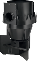
3P Hydroshark 1.500
FOR INSTALLATION IN A
CONCRETE SHAFT DN 1500
Connectable area full flow treatment
Category II*:
5,000 m²
Maximum treatment flow rate [l/s]**
167
Maximum hydrolic flow [l/s]***
228
Max. Nominal connection diameter DN****
500
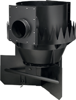
3P Hydroshark 2.000
FOR INSTALLATION IN A
CONCRETE SHAFT DN 2000
Connectable area full flow treatment
Category II*:
10,000 m²
Maximum treatment flow rate [l/s]**
250
Maximum hydrolic flow [l/s]***
416
Max. Nominal connection diameter DN****
600
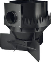
3P Hydroshark 2.500
FOR INSTALLATION IN A
CONCRETE SHAFT DN 2500
Connectable area full flow treatment
Category II*:
20,000 m²
Maximum treatment flow rate [l/s]**
500
Maximum hydrolic flow [l/s]***
832
Max. Nominal connection diameter DN****
700
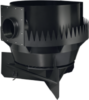
3P Hydroshark 3.000
FOR INSTALLATION IN A
CONCRETE SHAFT DN 3000
Connectable area full flow treatment
Category II*:
35,000 m²
Maximum treatment flow rate [l/s]**
875
Maximum hydrolic flow [l/s]***
1,100
Max. Nominal connection diameter DN****
700
* DN 1,500; AFS63 retention 48.0 %, IKT-tested on 19.04.2024
* DN 1,000; AFS63 retention 47.4 %, IKT-tested on 19.04.2024
* DN 2,000; AFS63 retention 48.7 %, tested on 22.04.2024
* DN 2,500; AFS63 retention 47.3 %, tested on 24.07.2024
* DN 3.000; AFS63 retention 47,51 %, tested on 01.10.2024
*** Rated rainfall rmax = 250 l/(s – ha)
**** Pipe diameter depends on the slope, can be individually adjusted
PLANNING CERTAINTY THROUGH APPROVALS
DESIGN ACCORDING TO
DWA-A102
DESIGN ACCORDING TO
DWA-M 153
TESTED IN ACCORDANCE WITH
TRENNERLASS NRW
LANUV-
LIST NRW

MEASUREMENT TOOL
FOR THE TREATMENT OF RAINWATER FOR YOUR PROPERTY IN ACCORDANCE WITH DWA-A 102/BWK-A 3-2
Determination of the appropriate treatment plant for discharge into surface waters.
TENDER SPECIFICATIONS &
DRAWINGS
Request your
tender texts and
drawings!
PLANNING TOOLS
Individual, needs-oriented &
up-to-date information
BIM DATA
Building information modeling
(Building Information Modelling, BIM) for
the provision of 3D and 2D data,
tender texts and other
information for your construction projects.
YOU NEED PROFESSIONAL
SUPPORT OR
HAVE QUESTIONS FOR US?

Jonas Bitterling, M. Eng.
Project Engineer
Tel +49 (0) 7334 92460-12
Mail bitterling@3ptechnik.de

Daniel Betschner,
Master Professional of
Technical Management (CCI)
Project Engineer
Tel +49 (0) 7334 92460-32
Mail betschner@3ptechnik.de
REFERENCES
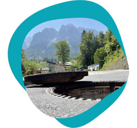
ZUGSPITZE
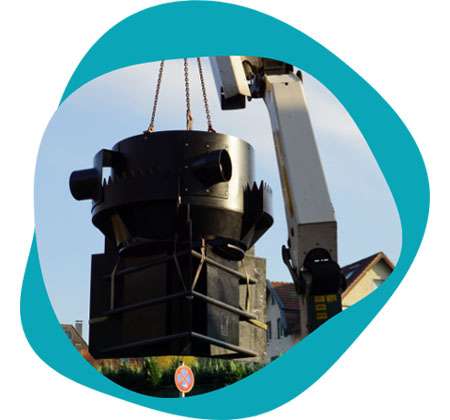
ECONOMIC ENTERPRISES HAGEN
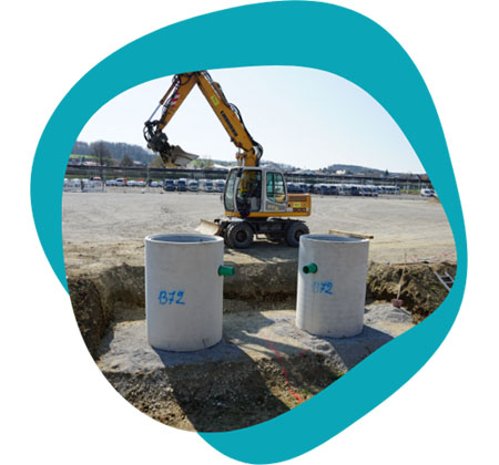
LOGISTICS CENTER DISTRICT OF BIBERACH
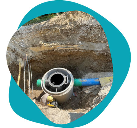
DEGGINGEN SPORTS GROUND
THOROUGHFARE EBERSBACH
AMAZON GIENGEN
FUNCTIONAL PRINCIPLE
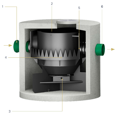
①
The water flows in tangentially in the middle of the hydrodynamic separator.
②
Solids settle to the bottom, floating matter remains on the water surface.
③
The solids are collected in the sludge trap, which is hydraulically separated from the treatment chamber by flow breakers and a grating to prevent remobilization.
④
The water rises evenly up the side walls.
⑤
The purified water is collected in an annular chamber via a serrated weir and then transported to the outlet.
⑥
The water runs off.
3D MODELL
THE HYDROSHARK
THE SEDIMENTATION PLANT SHOWING TEETH
The Hydroshark sedimentation system reliably removes filterable
substances (TSS) from stormwater runoff. It thus protects bodies of water and
infiltration systems.
Whereas in previous years, sewage treatment plants or agriculture were often the cause of water pollution, today it is rainwater discharges from polluted areas such as heavily trafficked traffic areas, industrial areas, parking lots or even metal roofs.
The loads are very different and are divided into categories in the DWA worksheets, for example. Depending on the sensitivity of the water, the need for treatment is then derived. Discharges into groundwater are viewed more critically, as groundwater is our drinking water resource of tomorrow.
For large areas of several hectares, for example, centralized treatment systems such as rainwater clarifiers or retention soil filters can be used for stormwater treatment. Decentralized treatment plants have become established for smaller areas, inner-city areas with little parking space or hotspots of pollution, e.g. at traffic light intersections. Different process technologies are used depending on the substance or substance group.
APPLICATION AREAS
Traffic areas
Roof surfaces
Special applications
Physical treatment of precipitation water.
Underground system, therefore no space required above ground.
Removal of solids (TSS).
No height offset between inlet and outlet.
Easy control and maintenance.
Different sizes.
No blocking possible.
