FILTRATION SYSTEM
3P HYDROSYSTEM 1.500
For areas with heavy traffic.
For metal roofs.
OVERVIEW HYDROSYSTEM / TECHNICAL DATA
heavy traffic
FOR HEAVILY LOADED
TRAFFIC AREAS DTV > 15,000
Connectable area:
1,600 m²
Flow rate:
Q = 16 l/s

metal
FOR METAL ROOF SURFACES
(COPPER, ZINC, LEAD)
Connectable area:
1,300 m²
Flow rate:
Q = 13 l/s
PLANNING CERTAINTY THROUGH APPROVALS
DIBT
APPROVAL
LFU METAL ROOF
APPROVAL
LANUV-LIST
NRW
VSA PERFORMANCE
AUDIT
EXTRACTION VIA
DWA-A 102
EXTRACTION VIA
DWA-M 153
EXTRACTION VIA
DWA-A 138
TENDER SPECIFICATIONS &
DRAWINGS
Request your
tender texts and
drawings!
PLANNING TOOLS
Individual, needs-oriented &
up-to-date information
BIM DATA
Building information modeling
(Building Information Modelling, BIM) for
the provision of 3D and 2D data,
tender texts and other
information for your construction projects.
YOU NEED PROFESSIONAL
SUPPORT OR
HAVE QUESTIONS FOR US?

Jonas Bitterling, M. Eng.
Project Engineer
Tel +49 (0) 7334 92460-12
Mail bitterling@3ptechnik.de

Daniel Betschner,
Master Professional of
Technical Management (CCI)
Project Engineer
Tel +49 (0) 7334 92460-32
Mail betschner@3ptechnik.de
REFERENCES
GFA NEUSS
INDUSTRIAL BUILDING
FUNCTIONAL PRINCIPLE
①
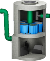
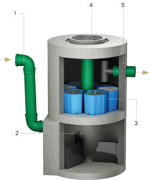
The stormwater from the area to be drained is discharged at the lower end of the shaft. The deflection aid deflects the water tangentially.
②
These are collected via an opening in the lower part of the cleaning shaft in a sludge trap with flow breakers under the system. The sludge trap is vacuumed out at intervals.
③
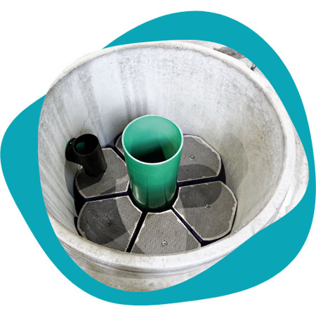
There are six filter elements in the middle of the manhole. These are used to filter the fines in an upflow process and a large proportion of the dissolved pollutants are precipitated and adsorbed. The filter can be backwashed from above and can be easily replaced if it becomes completely clogged.
④
The filter elements can be easily removed via the existing shaft opening.
⑤
The clean water is located above the filter elements. It passes through an oil barrier and then flows via the drain into the seepage system or a surface water body.
3D MODELL
HYDROSYSTEM 1.500
HIGH PERFORMANCE ON LARGE AREAS
The Hydrosystem 1.500 is installed in a concrete shaft with an internal diameter of DN 1500 at the factory.
A hydrodynamic separator causes the sedimentation of solids in a radial flow regime characterized by secondary flows. The effect of the separator causes the solids to enter the flow-calmed sludge trap located below the flow breaker. The 6 filter elements are located above the separator chamber. The water passes through the six filter elements in an upflow process. The system removes pollutants such as heavy metals, mineral oil hydrocarbons and polycyclic aromatic hydrocarbons from the rainwater. It also binds nutrients such as phosphates. The quality of the purified water is so high that it can be discharged directly into the infiltration system or any receiving waters.
The height difference between the inlet and outlet is only 25 cm. As the system is installed under the traffic surface, it does not require any additional space on the property or in the street. The treatment system can be used for traffic areas such as parking lots and roads of all traffic loads, industrial areas and metal roofs. Six different filter cartridges are available for this purpose.
FILTER VARIANTS
heavy traffic
For heavily loaded
traffic areas
metal
For metal roof surfaces
Cleaning of rainwater runoff from
traffic areas, industrial areas and metal roofs.
Shaft system, no space required on the surface.
Low height offset.
Easy control and maintenance.
